
![ULPP-501 dimension drawing, front and right side views: overall height 6.44 in [163.6 mm], diaphragm actuator Ø6.25 in [158.8 mm], ½-14 NPTF IN, CYL and EXH ports, ¼-18 NPTF pilot port, two Ø0.38 in mounting holes](/product-images/air-piloted-valves/ulpp-501-dimensions.webp)
ULPP-501Ultra Low Pilot Pressure 3-Way Air-Piloted Valve
3-way air-piloted valve with diaphragm actuator
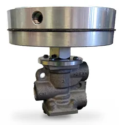
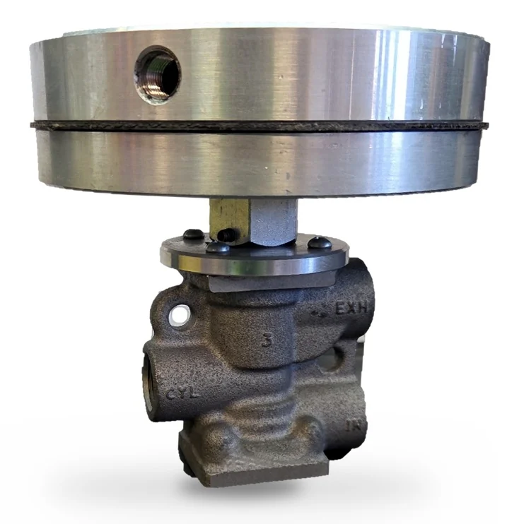
The ULPP-501 shifts a full-flow, 3-way poppet valve with a pilot signal of less than 5 psig, even at 125 psig line pressure. A large-area diaphragm actuator mounted directly on the relay valve multiplies a weak or remote pilot signal into the force needed to stroke the poppet, so no booster relay or intermediate pilot valve is required. Flow performance is unchanged from the standard relay body: a full 0.500-inch orifice, straight-line ½ NPTF plumbing and up to 275 scfm.
- Pilot pressure to shift
- < 5psig
- Supply pressure range
- 0–125psig
- Flow at 125 psig
- 275scfm
- Full-flow orifice
- 0.500in
Pricing on requestRequest a quote for the quantity you need
- Supplied complete with diaphragm actuator
- Four circuit functions from one valve: NC, NO, diverter or selector
- No booster relay or amplifier valve required
- Sales and service support from Edmonton, Alberta
Overview
Features
- Shifts on < 5 psig pilot at full 125 psig supply
- Full-flow relay body: 0.500 in orifice, 275 scfm
- Four circuits: normally closed, normally open, diverter or selector
- Straight-line ½ NPTF plumbing, ports in one plane
- Direct-coupled diaphragm actuator, ¼ NPTF pilot
- No booster relay or amplifier valve required
- Hard-coated aluminum body, Buna-N seals
- Mounts in any position
How it works
Pilot air at the ¼ NPTF port pressurizes the chamber above the diaphragm. Acting over roughly 21 in² of effective area, a few psig of pilot produces more than 100 lbf of thrust, which the hex coupling transmits to the relay valve’s poppet. The valve stays shifted while the pilot signal is held; when the pilot is exhausted, the return spring and line pressure reset it to its normal position. The chamber below the diaphragm vents to atmosphere and must be kept clear.
Typical applications
- Low-pressure sensing circuits: tank level, back-pressure and bleed-port sensing
- Weak, remote or long-line pilot signals
- Interfacing low-pressure pneumatic logic and instrument signals with high-flow power circuits
Specifications
| Type | 3-way, 2-position poppet, spring return |
|---|---|
| Media | Compressed air (consult factory for others) |
| Supply pressure | 0 to 125 psig (0 to 8.6 bar) |
| Ports: IN, CYL, EXH | ½-14 NPTF |
| Orifice | 0.500 in (12.7 mm) |
| Temperature range | –30 to 225 °F (–34.4 to 107.2 °C) |
| Materials | Hard-coated cast aluminum, zinc-plated steel, stainless steel, Buna-N |
| Mounting | Any position; two Ø0.38 in holes |
| Lubrication | Recommended |
| Filtration | Recommended |
| Type | Single-acting diaphragm, direct-coupled |
|---|---|
| Pilot port | ¼-18 NPTF |
| Pilot pressure to shift | < 5 psig (0.34 bar) at 0 to 125 psig supply |
| Maximum pilot pressure | 140 psig (9.7 bar) |
| Effective diaphragm area | ≈ 21 in² (135 cm²) |
| Thrust | ≈ 21 lbf per psig of pilot (≈ 105 lbf at 5 psig) |
| Pilot chamber volume | ≈ 5 in³ (82 cm³) |
| Housing | Machined aluminum, two-piece |
| Diaphragm | Fabric-reinforced Buna-N |
| Coupling / fasteners | Brass hex coupling; black-oxide steel screws |
Circuit functions
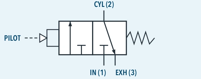
One valve, four circuits: the function is set by how the IN, CYL and EXH ports are plumbed.
| Function | Port connections | Pilot signal removed | Pilot signal applied |
|---|---|---|---|
| Normally closed | Supply to IN · CYL to work · EXH vents | IN blocked; CYL exhausts through EXH | IN flows to CYL; EXH blocked |
| Normally open | Supply to EXH · CYL to work · IN vents | Supply flows EXH to CYL | Supply blocked; CYL exhausts through IN |
| Diverter | Supply to CYL · IN and EXH are outlets | CYL flows to EXH outlet | Flow diverted to IN outlet |
| Selector (bi-media) | Supply A to EXH · Supply B to IN · CYL is common outlet | CYL receives supply A | CYL receives supply B |
Performance
Air flow to atmosphere
| Model | At 30 psig (2.1 bar) | At 120 psig (8.3 bar) | ||
|---|---|---|---|---|
| CFM | LPM | CFM | LPM | |
| ULPP-501 | 72.0 | 2037.6 | 267.0 | 7556.1 |
Fill / exhaust times (seconds)
| Supply pressure | 50 psig (3.5 bar) | 100 psig (7.0 bar) | ||||||
|---|---|---|---|---|---|---|---|---|
| Chamber volume | 10 in³ (164 cc) | 100 in³ (1640 cc) | 10 in³ (164 cc) | 100 in³ (1640 cc) | ||||
| Model | Fill | Exhaust | Fill | Exhaust | Fill | Exhaust | Fill | Exhaust |
| ULPP-501 | 0.008 | 0.012 | 0.082 | 0.096 | 0.009 | 0.015 | 0.094 | 0.119 |
Fill: chamber charged from 0 to 40 psig (50 psig supply) or 0 to 80 psig (100 psig supply). Exhaust: chamber vented from 50 to 10 psig or 100 to 20 psig. Times are for the relay valve and do not include actuator pilot fill time, which depends on pilot line size and length.
Weight
| Assembly | lb | kg |
|---|---|---|
| Relay valve only | 0.9 | 0.4 |
| ULPP-501 complete | ≈ 5.5 | ≈ 2.5 |
Dimensions
Downloads and ordering
 Product data sheetULPP-501 product data sheet Download PDF
ULPP-501
Ultra Low Pilot Pressure 3-way air-piloted valve, complete with diaphragm actuator.
- ½-14 NPTF IN / CYL / EXH ports
- ¼-18 NPTF pilot port
- Shifts on < 5 psig pilot
Questions about the ULPP-501?
Tell us about your pilot signal, supply pressure and circuit, and we'll confirm the fit and send you a quote.